Search This Blog

Friday, April 11, 2014

Video Learning Series : Interfacing LED & Switch ::: Task - 3 with Codes & Video


 Video Learning Series : Interfacing LED & Switch ::: Task - 3


https://www.youtube.com/watch?v=P5hYdB_n6xo&list=UU91Msf7ixvSGlnx_RsKTd7Q
Click Here For Video ::: Video Learning Series (vhdlbynaresh.blogspot.com)


Video Link -
https://www.youtube.com/watch?v=P5hYdB_n6xo&list=UU91Msf7ixvSGlnx_RsKTd7Q


TASK 3  ::::    Interfacing LED & Switch With Cyclone II FPGA Device. -
Description -    LED's Starts Blinking when Switch is pressed & Remains same as it's last update when Switch is released.
In our video we take 8 LED's as output packed in 7- segment package.


VHDL Code -


library ieee;
use ieee.std_logic_1164.all;
use ieee.std_logic_arith.all;
use ieee.std_logic_unsigned.all;

entity sl3 is
port (clk : in std_logic;
din : in std_logic;
dout : out std_logic_vector (7 downto 0));
end sl3;

architecture sl2_arc of sl3 is
begin
    p0 : process (clk,din) is
    variable m : std_logic_vector (24 downto 0) := (others=>'0');
    begin
        if (rising_edge (clk)) then
            m := m + 1;
        end if;
        if (din='0') then
            case m(24) is
                when '0' => dout <= "00000000";
                when others => dout <= "11111111";
            end case;
        end if;
    end process p0;
       
end sl2_arc;


Please revert with your suggestions, likes and comments to make this video series successful and helpful to others.

I would love to read your suggestions and comments here below

Best Regard //
Naresh Singh Dobal
nsdobal@gmail.com


Video Learning Series : Interfacing LED & Switch ::: Task - 2 with Codes & Video


 Video Learning Series : Interfacing LED & Switch ::: Task - 2


https://www.youtube.com/watch?v=rmpQ8F0dziY&list=UU91Msf7ixvSGlnx_RsKTd7Q   
Click Here For Video  ::: Video Learning Series (vhdlbynaresh.blogspot.com)


Video Link  -
https://www.youtube.com/watch?v=rmpQ8F0dziY&list=UU91Msf7ixvSGlnx_RsKTd7Q


 TASK 2  ::::    Interfacing LED & Switch With Cyclone II FPGA Device. -
Description -    LED's Starts Blinking when Switch is pressed & goes OFF when Switch is released.
In our video we take 8 LED's as output packed in 7- segment package.


VHDL Code -


library ieee;
use ieee.std_logic_1164.all;
use ieee.std_logic_arith.all;
use ieee.std_logic_unsigned.all;

entity sl2 is
port (clk : in std_logic;
din : in std_logic;
dout : out std_logic_vector (7 downto 0));
end sl2;

architecture sl2_arc of sl2 is  --frequncy is 50 MHz
begin
    p0 : process (clk,din) is
    variable m : std_logic_vector (24 downto 0) := (others=>'0');
    begin
        if (rising_edge (clk)) then
            m := m + 1;
        end if;
        if (din='0') then
            case m(24) is
                when '0' => dout <= "00000000";
                when others => dout <= "11111111";
            end case;
        else
            dout <= (others => '0');
        end if;
    end process p0;
       
end sl2_arc;


 Please revert with your suggestions, likes and comments to make this video series successful and helpful to others.

I would love to read your suggestions and comments here below

Best Regard //
Naresh Singh Dobal
nsdobal@gmail.com

Video Learning Series : Interfacing LED & Switch ::: Task - 1 with Codes & Video


Video Learning Series : Interfacing LED & Switch  :::  Task - 1


https://www.youtube.com/watch?v=Ea_N3f_JQMc&list=UU91Msf7ixvSGlnx_RsKTd7Q
Click Here For Video ::: Video Learning Series (vhdlbynaresh.blogspot.com)


Video Link  - 
https://www.youtube.com/watch?v=Ea_N3f_JQMc&list=UU91Msf7ixvSGlnx_RsKTd7Q


 TASK 1  ::::    Interfacing LED & Switch With Cyclone II FPGA Device. - 
Description -    LED goes  ON when Logic 1 is given by switch as input & goes OFF when Logic '0' is given by switch as input.
In our video we take 8 LED's as output packed in 7- segment package.


VHDL Code -  

library ieee;
use ieee.std_logic_1164.all;

entity sl1 is
port (din : in std_logic ;
dout : out std_logic_vector (7 downto 0));
end sl1;

architecture sl1_arc of sl1 is
begin

dout <= "00000000" when din='0' else
"11111111";

end sl1_arc;


Please revert with your suggestions, likes and comments to make this video series successful and helpful to others.

I would love to read your suggestions and comments here below
Best Regard //
Naresh Singh Dobal
nsdobal@gmail.com

Tuesday, November 19, 2013

VHDL Lab Exercises...


VHDL Lab Exercise...

Learn VHDL with Naresh Singh Dobal Test Series...


1.  LAB Exercise 1             (Combinational System Design using Gates).

2.  LAB Exercise 2             (Combinational System Design data flow).

3.  LAB Exercise 3             (Combinational System Design using Behavior Model).

4.  LAB Exercise 4             (Flip Flop & Latches Design using Behavior Model).

5.  LAB Exercise 5             (Counters & Frequency Dividers Design using Behavior Model).

6.  LAB Exercise 6             (Hardware Peripherals &  System Design using Behavior Model).

7.  LAB Exercise 7             (Combinational System Design using Structural Model).

8.  LAB Exercise 8             (Flip Flop & Shift register design using Structural Model).


I also linked Solutions for most of the assignment
If you feel any difficulties in any assignment then you can follow the links mentioned in the last of assignment pages...


I would love to read your suggestions and comments here below.
My name is Naresh Singh Dobal, for any query contact us at nsdobal@gmail.com

VHDL Lab Exercise ::: Exercise 8


VHDL Lab Exercise   :::   Exercise 8

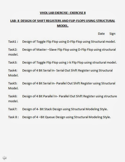
LAB- 8  DESIGN OF SHIFT REGISTERS AND FLIP-FLOPS USING STRUCTURAL MODEL.


VHDL Lab Exercise 8 :: VHDL with Naresh Singh Dobal Learning Series.


If you feel any difficulties in any assignment then follow the below link...


I would love to read your suggestions and comments here below.
My name is Naresh Singh Dobal, for any query contact us at nsdobal@gmail.com

VHDL Lab Exercise ::: Exercise 7


VHDL Lab Exercise   :::   Exercise 7


LAB5  COMBINATIONAL SYSTEM DESIGN USING STRUCTURAL MODEL.


VHDL Lab Exercise 7 :: VHDL with Naresh Singh Dobal Learning Series.


If you feel any difficulties in any assignment then follow the below link...


I would love to read your suggestions and comments here below.
My name is Naresh Singh Dobal, for any query contact us at nsdobal@gmail.com

VHDL Lab Exercise ::: Exercise 6


VHDL Lab Exercise   :::   Exercise 6

LAB 6 : HARDWARE PERIPHERALS  & SYSTEM DESIGNS.


Lab Exercise 6 :: VHDL with Naresh Singh Dobal Learning Series.


If you feel any difficulties in any assignment then follow the below link...


I would love to read your suggestions and comments here below.
My name is Naresh Singh Dobal, for any query contact us at nsdobal@gmail.com

VHDL Lab Exercise ::: Exercise 5


VHDL Lab Exercise   :::   Exercise 5

LAB5 : COUNTERS AND FREQUENCY DIVIDERS.


Lab Exercise 5 : VHDL with Naresh Singh Dobal Learning Series.


If you feel any difficulties in any assignment then follow the below link...


I would love to read your suggestions and comments here below.
My name is Naresh Singh Dobal, for any query contact us at nsdobal@gmail.com

VHDL Lab Exercise ::: Exercise 4


VHDL Lab Exercise   :::   Exercise 4 -


LAB4 : LATCHES & FLIP-FLOPS & ALU.


Lab Exercise 4 : VHDL with Naresh Singh Dobal Learning Series.


If you feel any difficulties in any assignment then follow the below link...


I would love to read your suggestions and comments here below.
My name is Naresh Singh Dobal, for any query contact us at nsdobal@gmail.com

VHDL Lab Excercise ::: Exercise 3


VHDL Lab Exercise   :::   Exercise 3 -

LAB 3 : COMBINATIONAL SYSTEM DESIGN USING BEHAVIOR MODELLING STYLE.


Lab Exercise 3 :  VHDL with Naresh Singh Dobal Learning Series.
Lab Exercise 3-b ::  VHDL with Naresh Singh Dobal Learning Series.


Task1 :      Write a VHDL code for Full adder using if-else.
Task2:       Write a VHDL code for Full subtractor using if-else.
Task3:       Write a VHDL code for 4:1 Multiplexer using if-else.
Task4:       Write a VHDL code for 1:4 Demultiplexer using if-else.
Task5:       Write a VHDL code for a 8:3 Encoder using if-else.
Task6:       Write a VHDL code for a 3:8 Decoder using if-else.
Task7:       Write a VHDL code for Full adder using case.
Task8 :      Write a VHDL code for Full subtractor using case.
Task9:       Write a VHDL code for 4:1 Multiplexer using case.
Task10:     Write a VHDL code for 1:4 Demultiplexer using case.
Task11:     Write a VHDL code for 8:3 Encoder using case.
Task12:     Write a VHDL code for 3:8 Decoder using case.
Task13:     Write a VHDL code for 3 bit comparator using if-else.
Task14:     Write a VHDL code for BINARY TO GRAY converter using if-else.
Task15:     Write a VHDL code for GRAY TO BINARY converter using case.


If you feel any difficulties in any assignment then follow the below link...


I would love to read your suggestions and comments here below.
My name is Naresh Singh Dobal, for any query contact us at nsdobal@gmail.com

VHDL Lab Exercise ::: Exercise 2


VHDL Lab Exercise   :::   Exercise 2 -

LAB2 : COMBINATIONAL SYSTEM DESIGN USING DATA FLOW MODELLING STYLE.

Lab Exercise 2a :: VHDL with Naresh Singh Dobal Learning Series.
Lab Exercise 2-b :: VHDL with Naresh Singh Dobal Learning Series.


Task1 :      Write a VHDL code for all gates using with-select.
Task2:       Write a VHDL code for Full adder using with-select.
Task3:       Write a VHDL code for Full subtractor using with-select. .
Task4:       Write a VHDL code for 4:1 Multiplexer using With-select.
Task5:       Write a VHDL code for a 1:4 Demultiplexer using with-select.
Task6:       Write a VHDL code for a 8:3 Encoder using With-Select.
Task7:       Write a VHDL code for a 3:8 Decoder using With-Select.
Task8 :      Write a VHDL code for all gates using when-else.
Task9:       Write a VHDL code for Full adder using when-else.
Task10:     Write a VHDL code for Full subtractor using when-else.
Task11:     Write a VHDL code for 4:1 Multiplexer using When-else. .
Task12:     Write a VHDL code for a 1:4 Demultiplexer using when-else.
Task13:     Write a VHDL code for a 8:3 Encoder using When-else.
Task14:     Write a VHDL code for a 3:8 Decoder using When-else.
Task15:     Write a VHDL code for 8:3 Encoder with Priority using when-else.
Task16:     Write a VHDL code for BINARY to GRAY Converter using with-select.
Task17:     Write a VHDL code for GRAY to BINARY Converter using with-select.
Task18:     Write a VHDL code for BINARY to GRAY Converter using when-else.
Task19:     Write a VHDL code for GRAY to BINARY Converter using when-else.
Task20:     Write a VHDL code for BINARY to EXCESS-3 using With-select.
Task21:     Write a VHDL code for BINARY TO GRAY Converter using equation.
Task22:     Write a VHDL code for GRAY to BINARY Converter using equations.
Task23:    Write a VHDL code for BINARY TO EXCESS-3 using equations.


If you feel any difficulties in any assignment then follow the below link...


I would love to read your suggestions and comments here below.
My name is Naresh Singh Dobal, for any query contact us at nsdobal@gmail.com

VHDL Lab Exercise :: Exercise 1


VHDL Lab Exercise   :::   Exercise 1 -


LAB 1:  COMBINATIONAL SYSTEM DESIGN USING BASIC GATES AND EQUATIONS.
VHDL Lab Exercise 1 :: VHDL with Naresh Singh Dobal Learning Series.


Task1 :   Write a VHDL Program for all Logic Gates.
Task2 :   Write a VHDL code for a Half Adder using Digital Electronics.
Task3 :   Write a VHDL code for a Full Adder using Digital Electronics.
Task4 :   Write a VHDL code for a Half Subtractor using Digital Electronics.
Task5 :   Write a VHDL code for a Full Subtractor using Digital Electronics.
Task6:    Write a VHDL code for a 4:1 Multiplexer using Digital Electronics.
Task7:    Write a VHDL code for a 1:4 Multiplexer using Digital Electronics.
Task8:    Write a VHDL code for a 4:2 Encoder using Digital Electronics.
Task9:    Write a VHDL code for a 2:4 Decoder using Digital Electronics.
Task10:  Write a VHDL code for 1 bit Comparator using Digital Electronics. 


If you feel any difficulties in any assignment then follow the below link...


I would love to read your suggestions and comments here below.
My name is Naresh Singh Dobal, for any query contact me at nsdobal@gmail.com

Tuesday, November 12, 2013

A Small Discussion about VHDL & Verilog HDL...


A Small Discussion about VHDL & Verilog HDL -


VHDL or Verilog HDL - A small discussion (VHDL with Naresh Singh Dobal learning Series).


Verilog HDL is easier to understand and use, It is very effectively used for simulation and synthesis. but it lacks for system level or complex designing. It is promoted by OVI (Open Verilog International). It is widely used for ASIC designing or lower level design (RTL or  lower), but this results in faster simulation and effective synthesis. Mostly used in North America, Asia & Japan, but not popular in Europe.

As comparable to verilog HDL, VHDL is more complex, thus difficult to learn and use. But this offers more flexibility of designing. Since VHDL is better suited for handling very complex systems, so it is now gaining popularity. VHDL  is mainly promoted by VHDL international. VHDL is relatively weaker in lower designs. But superior in system level design. Many believes that in long terms presents better condition and adaptability than its competitors. This language is widely used in Europe, significantly used in US and Canada, but this disliked in Japan...


Both the HDL's are used to describe electronic systems.
The function of systems is to get input data from it's environment and give output some data in return.
In verilog HDL this is called a module which is a basic building block in Verilog HDL, and in VHDL this is defined in Entity & Architecture Pair.
 Both the Languages are IEEE Standard.


I would love to read your suggestions and comments here below,
Best Regard //
Naresh Singh Dobal
nsdobal@gmail.com